We are the only authorised distributor for all ranges of SUNNIK Sectional Panel Tanks in the United Kingdom.
Pressed steel sectional water tank constructed with hydraulically pressed flanged panels, conform to BS 1564 : 1975
Material: The steel used in the manufacture of the tank plates, stays and cleats conform to the requirements of BS 4360 : 1972 grade 43A or ISO equivalent
Flanges of Plates: The tank plates are pressed with a combined double flange at an angle of 45 degree and 90 degree to the face of the plate on four sides
1.3 Reinforcement Method: All tanks are internally braced with angle stays to endure the rigidity of the tank when filled with the water.
Stays and Cleats:The stays and cleats are made of steel angle bar and steel plate
Bolts, Nuts and Washers: Hot Dipped Galvanised steel bolts, nuts and washers for internal and external
Jointing Materials: Non toxic PVC foam to be used for all jointing between tank panel flange
Tank Cover: Panel type or pitched type steel cover supported by trusses 600 x 600 square manhole and 100mm air-vent supplied as standard for each compartment
Water Level Indicator: Mechanical Ball Float Type
Ladder: Aluminium or HDG Steel ladder for internal and external access
Finish : (a) Hot Dip Galvanised conform to BS 729 or ISO equivalent (b) Black Bituminous Coated.
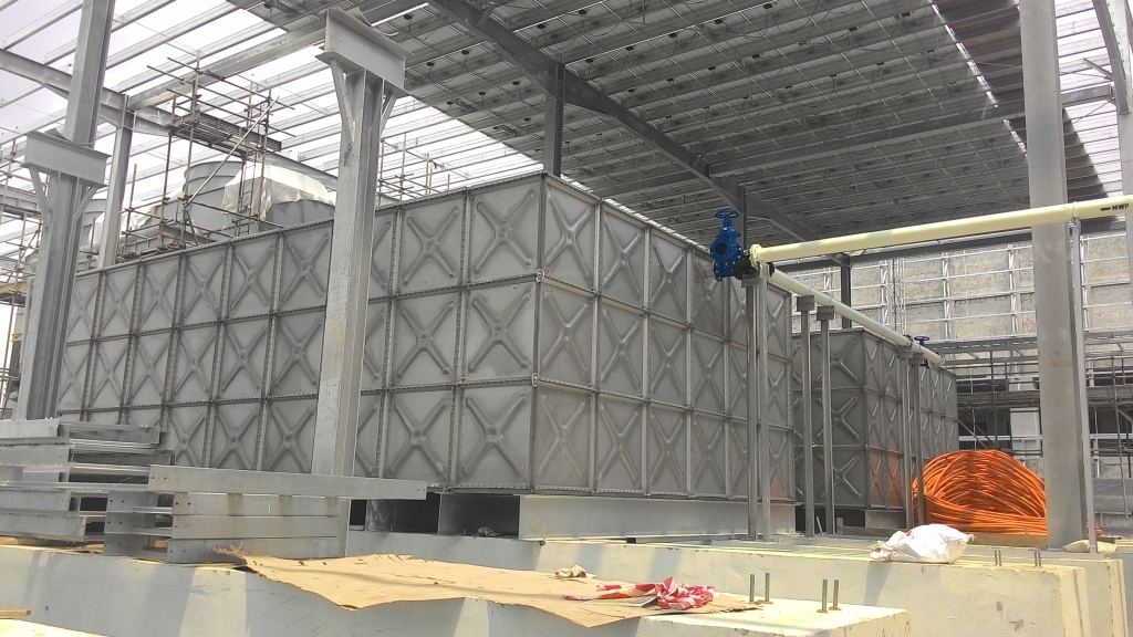
PRESSED STEEL SECTIONAL RECTANGULAR TANKS Scope/
This British Standard specifies requirement for pressed steel sectional rectangular tanks, working under a pressure not greater than the static head corresponding to the depth of the tanks, built up of pressed steel plates 1220mm square used to contain cold water, hot water, potable liquids, certain oils and chemicals. Tanks may be constructed as follows:
(a) with external flanges,
(b) with internal bottom flanges, external side and end flanges.
Two types are specified:
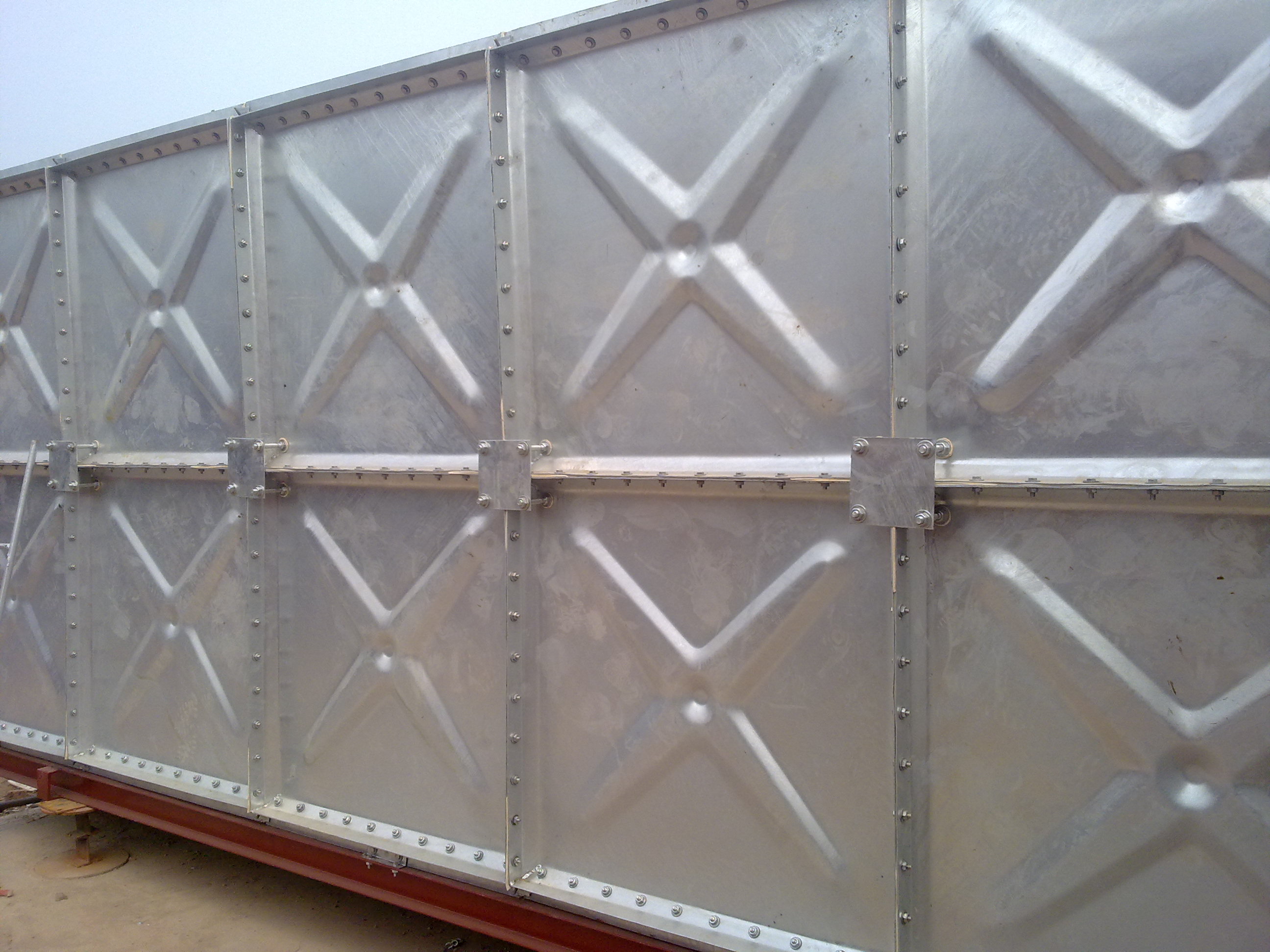
Type 1. With a combined double flange at an angle of 45° and 90° to the plane of the plate on all four sides as illustrated in figure 1. The plates of type 1 tanks are hot pressed complete.
Type 2. With a single flange at an angle of 90° to the plane of the plate on each of two, three or four sides, depending on its position in the tank. Type 2 tanks are cold pressed as illustrated in figure 2, with the flange corners welded. This standard does not provide for tanks subject to earth or other external pressure other than wind pressure.
NOTE. For an illustration of a typical tank external flanges see figure 8. For approximate weights and full nominal capacities (without freeboard) of open top tanks see tables 1 to 4.
Tanks can also be assembled with all flanges internal with the addition of other components, but because of the difficulty of assembling and maintaining this type of tank they are not preferred.
All tanks can be supplied with open or closed top. Information on erection and supports is also included.
References
The titles of the British Standards referred to in this standard are listed on the inside back cover.
Information to be supplied with the enquiry and order
The following information, as appropriate, should be supplied by the purchaser with his enquiry or order.
(a) Type of tank required (clause 1), type of cover (if any), number and position and type of manhole(s), number of divisions if required.
(b) Capacity required in litres or dimensions in millimetres in multiples of 1220 mm and whether any provision is to be made for future extension and if any level indicators are required.
(c) Limiting conditions, if any, as to space and accessibility for erection, and whether the tank will be erected in a building or exposed to the weather and the height above ground level it is to be installed.
(d) Nature and density of liquid for which the tank is required. If corrosive, particulars to be given. If water, state whether hard or soft. The rate of filling and emptying the tank, head fluctuations and cycles per day.
(e) Maximum and minimum temperatures and approximate rate of fluctuation and position of heating elements.
(f) Any special requirements as to jointing material and as to internal and external coating or lagging. NOTE: In the absence of any special requirements one coat of suitable priming paint will be applied to protect the tank during delivery and erection. A minimum of two further coats should be applied after erection.
(g) Particulars of connections and drilling required and precise location on tank with dimensioned sketches, having regard to possible future requirements.
(h) Whether external access ladders are required and, if so, particulars to be given.
(i) Details of any existing or proposed supporting structure and height of bottom of tank above ground level so that the necessary scaffolding arrangements can be made to comply with statutory safety regulations.
(j) Whether transverse supporting bearers are required and, if so, particulars as to span and end support to be given.
(k) Whether the tank is to be used for other than a stationary application.
(l) Whether inspection will be made by the representative of the purchaser at the works of the manufacturer.
(m) Whether erection is to be carried out by the manufacturer at site; if so, information as to site conditions and accessibility to be given by the purchaser. Working temperatures
For the purpose of this standard cold liquids are defined as those having a temperature not exceeding 38 °C and hot liquids are defined as those having a temperature exceeding 38 °C but less than 100 °C.
In the case of tanks to hold hot liquids, care shall be taken in use to avoid excessive vibration or turbulence. Tanks for temperatures higher than 100 °C should be the subject of mutual arrangement between the purchaser and the manufacturer.
Materials 5.1 The steel used in the manufacture of the plates, stays, cleats and pads for connections shall conform to the requirements of BS 4360: 1972 grade 43A or BS 1449: Part 1: 1972 material HR 14.
5.2 Bolts, studs, nuts and washers shall be made from steel complying with the requirements of BS 4190. Bolts and nuts shall be hexagonal, black finish, screwed ISO metric complying with the requirements of BS 4190, where applicable. Washers shall comply with the requirements of BS 4320: 1968 from 'F'.
Dimensions of unit plates The nominal size of unit plates shall be 1200 mm square, the actual overall dimensions depending upon the particular manufacturer of the plates. The size of tanks shall be specified as multiples of the nominal dimension.
Thickness of unit plates For cold liquids with a density not exceeding 1.0 the nominal thickness of the plate from which the unit plates are pressed shall be not less than: mm Tanks 1220mm in depth: Bottom, sides and ends. 5 Tanks 2440 mm in depth: bottom, sides and ends. 5 Tanks 3660 mm in depth: bottom, sides and ends. 5 Tanks 4880 mm in depth: bottom, and first tier of sides & ends 6 second, third and top tiers of sides and ends 5 7.2 For hot liquids with a density not exceeding 1.0 no plate shall less than 6 mm in thickness.
7.3 For cold or hot liquids with a density greater than 1.0 the plate thicknesses shall be a matter for mutual arrangement between the purchaser and the manufacturer
Permissible stresses The calculated stress in any stay and attachment and bolts shall comply with the requirements of BS 449, and any allowance that may be required for corrosion shall be added to the calculated thickness.
Flanges of plate Plate shall be pressed with a combined double flange at an angle of 45 degree and 90 degree to the face of the plate on all four sides (type 1 figure 1) or a single flange at an angle of 90 degree to the plate on each of two, three or four sides (type 2 figure 2), the flanges holed according to the respective position of the plate in the tank and free from irregularities.
The width of the flanges shall be not less than 45 mm, the holes for the bolts having a clearance of 1.5 mm in diameter, the bolts having a minimum diameter of 14 mm (M14). The spacing of bolts holes shall not exceed 76.2 mm pitch.
Jointing material
The jointing to be used for tanks shall be suitable for the conditions and shall be a matter for mutual agreement between the purchaser and manufacturer. Any jointing used shall be insoluble in the liquid to be stored and, where necessary, shall be non-toxic.
Bolts, studs, nuts and washers Bolts, studs nuts and washers shall be in accordance with the requirement specified in 5.2. Each flange bolts shall be fitted with one flat washer under the nut and the diameter of the bolts shall be not less than 14 mm (M14
Staying The sides and ends of all tanks shall be supported by stays at the junction of two or more plates the stays shall made from mild steel rolled sections calculated in accordance with clause 7. Stays shall be attached to the plates by bolting to cleats of equal strength bolted to tank plates; stay attachments to cleats and cleats to tank plates shall be calculated taking into account eccentricity of loading. The ends of the stays shall be attached to the cleats or tank plates by bolts. Stays shall connect sides to bottom, ends to bottom and/or horizontally sides and sides to ends generally in accordance with figure 8.
Connections Pads for connections, tapped bosses, screwed flanges or sockets, as may be required by the purchaser, shall be welded to the inside or outside or bolted to the tank plate. Pads shall be drilled, and/ or tapped as necessary to suit flanges complying with the requirements of BS4504, or such other standard as specified by the purchaser. Single pads shall be provided for connection on one side of the plate and double pads for connection on both sides of the plate. Tapped socks shall comply with the requirements specified in BS 1387. Typical types of welded connections are shown in figures 3 to 7.
Welding of connections Welds for connections shall be made by the metal are process complying with the requirements of BS 1856 and by means of covered electrodes complying with the requirements of BS 639: 1972 sections 1 and 2 : grade 1
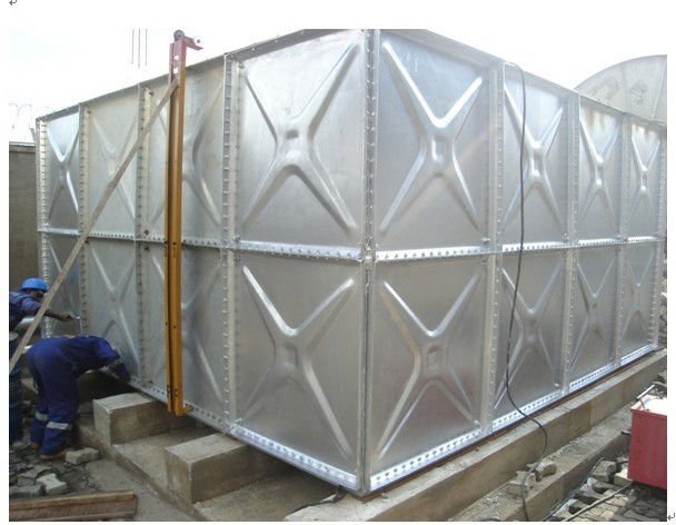
Supports All tanks shall effectively supported in accordance with the manufacturer's recommendations and tolerances. Supports shall he provided continuously under each bottom flange in one direction at 1220 mm centres. Tanks with internal bottom flanges can also rest directly on a flats level base. A sand/bitumen bed 50 mm thick is recommended in that case. Where steel joists are used they shall be designed to carry the imposed load with a maximum deflection of one five-hundredth of the span. Attention is drawn to the extra reaction on the supports under the side, end and division plates when the stays of sides, ends and divisions are inclined to the bottom of the tank.
Closed top tanks Cover framing members shall be designed to withstand superimposed loadings complying with the requirements of BS 449. Covers may be flat indoor use and should he pitched or cambered for outdoor use, and jointed to ensure that they are dust and weather proof. Covers may be constructed of steel plates or other constructional cladding materials. In all cases closed top tanks shall be provided with a manhole of not less than 460 mm diameter clear opening to give access to the inside of the tank and with a suitable vent, filtered if necessary, to the manufacturer's requirements to avoid pressure changes within the tank
Access Ladders Tanks over 1220mm deep shall be provided with a steel internal access ladder. In covered tanks the ladder shall be adjacent to the manhole. NOTE. External ladders may he provided required, attention is drawn to BS 4211
Marking All tanks complying with the requirements of this standard shall be legibly marked as follows.
(a) Manufacturer’s name, mark or initial.
(h) The number of this British Standard, i.e. BS 1564.
Minimum access Where tanks with external flanges are to be erected in a confined space it is essential that a clearance of not less than 500 mm shall be provided all round the outside and underneath to facilitate erection. For access to the top of a closed tank the clearance at the top shall be not less than 750 mm. NOTE. Allowance should be made for inspection and maintenance including valves or other external fittings.
Inspection Works inspection. The purchaser or his representative shall have access to the works of the manufacturer at all reasonable times and shall be at liberty to inspect and to reject any material which does not comply with the requirements of this standard. Such inspection shall include verification that the unit plates will mate together and assemble. Where partial or complete assembly is required at the works of the manufacturer, this shall be the subject of specific arrangement between the purchaser and the manufacturer at the time of enquiry and order.
Site inspection. The purchaser or his representative shall ensure that supports are within the tolerances required by the manufacturer before the commencement of erection
Erection Erection shall be carried out in accordance with the manufacturer's instructions
Testing Testing shall be filling the tank with water on site and shall be the subject of specific arrangement between the purchaser and the manufacturer at the time of the enquiry and order. Water for testing shall be supplied by the purchaser.