Flow measurement is the quantification of bulk fluid movement. Flow can be measured in a variety of ways. Positive-displacement flow meters accumulate a fixed volume of fluid and then count the number of times the volume is filled to measure flow. Other flow measurement methods rely on forces produced by the flowing stream as it overcomes a known constriction, to indirectly calculate flow. Flow may be measured by measuring the velocity of fluid over a known area.
A positive displacement meter may be compared to a bucket and a stopwatch. The stopwatch is started when the flow starts, and stopped when the bucket reaches its limit. The volume divided by the time gives the flow rate. For continuous measurements, we need a system of continually filling and emptying buckets to divide the flow without letting it out of the pipe. These continuously forming and collapsing volumetric displacements may take the form of pistons reciprocating in cylinders, gear teeth mating against the internal wall of a meter or through a progressive cavity created by rotating oval gears or a helical screw.
Because they are used for domestic water measurement, piston meters, also known as rotary piston or semi-positive displacement meters, are the most common flow measurement devices in the UK and are used for almost all meter sizes up to and including 40 mm (1 1⁄2 in). The piston meter operates on the principle of a piston rotating within a chamber of known volume. For each rotation, an amount of water passes through the piston chamber. Through a gear mechanism and, sometimes, a magnetic drive, a needle dial and odometer type display are advanced.
An oval gear meter is a positive displacement meter that uses two or more oblong gears configured to rotate at right angles to one another, forming a T shape. Such a meter has two sides, which can be called A and B. No fluid passes through the center of the meter, where the teeth of the two gears always mesh. On one side of the meter (A), the teeth of the gears close off the fluid flow because the elongated gear on side A is protruding into the measurement chamber, while on the other side of the meter (B), a cavity holds a fixed volume of fluid in a measurement chamber. As the fluid pushes the gears, it rotates them, allowing the fluid in the measurement chamber on side B to be released into the outlet port. Meanwhile, fluid entering the inlet port will be driven into the measurement chamber of side A, which is now open. The teeth on side B will now close off the fluid from entering side B. This cycle continues as the gears rotate and fluid is metered through alternating measurement chambers. Permanent magnets in the rotating gears can transmit a signal to an electric reed switch or current transducer for flow measurement. Though claims for high performance are made, they are generally not as precise as the sliding vane design.
Helical gear flow meters get their name from the shape of their gears or rotors. These rotors resemble the shape of a helix, which is a spiral-shaped structure. As the fluid flows through the meter, it enters the compartments in the rotors, causing the rotors to rotate. Flowrate is calculated from the speed of rotation.
This is the most commonly used measurement system for measuring water supply in houses. The fluid, most commonly water, enters in one side of the meter and strikes the nutating disk, which is eccentrically mounted. The disk must then "wobble" or nutate about the vertical axis, since the bottom and the top of the disk remain in contact with the mounting chamber. A partition separates the inlet and outlet chambers. As the disk nutates, it gives direct indication of the volume of the liquid that has passed through the meter as volumetric flow is indicated by a gearing and register arrangement, which is connected to the disk. It is reliable for flow measurements within 1 percent.
The variable area (VA) meter, also commonly called a rotameter, consists of a tapered tube, typically made of glass, with a float inside that is pushed up by fluid flow and pulled down by gravity. As flow rate increases, greater viscous and pressure forces on the float cause it to rise until it becomes stationary at a location in the tube that is wide enough for the forces to balance. Floats are made in many different shapes, with spheres and spherical ellipses being the most common. Some are designed to spin visibly in the fluid stream to aid the user in determining whether the float is stuck or not. Rotameters are available for a wide range of liquids but are most commonly used with water or air. They can be made to reliably measure flow down to 1% accuracy.
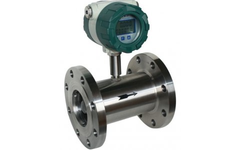
The turbine flow meter (better described as an axial turbine) translates the mechanical action of the turbine rotating in the liquid flow around an axis into a user-readable rate of flow (gpm, lpm, etc.). The turbine tends to have all the flow traveling around it.
.The turbine wheel is set in the path of a fluid stream. The flowing fluid impinges on the turbine blades, imparting a force to the blade surface and setting the rotor in motion. When a steady rotation speed has been reached, the speed is proportional to fluid velocity.
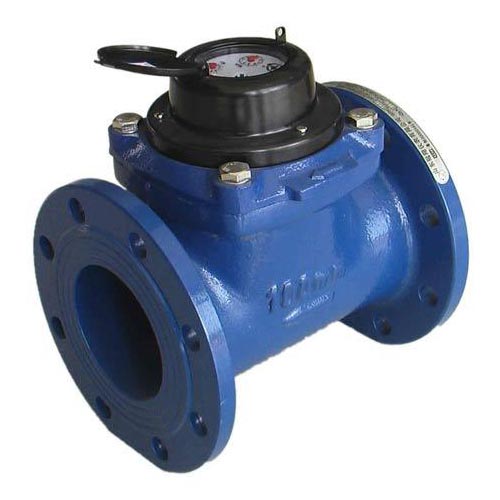
Turbine flow meters are used for the measurement of natural gas and liquid flow. Turbine meters are less accurate than displacement and jet meters at low flow rates, but the measuring element does not occupy or severely restrict the entire path of flow. The flow direction is generally straight through the meter, allowing for higher flow rates and less pressure loss than displacement-type meters. They are the meter of choice for large commercial users, fire protection, and as master meters for the water distribution system. Strainers are generally required to be installed in front of the meter to protect the measuring element from gravel or other debris that could enter the water distribution system. Turbine meters are generally available for 4 to 30 cm or higher pipe sizes. Turbine meter bodies are commonly made of bronze, cast Iron, or ductile iron. Internal turbine elements can be plastic
or non-corrosive metal alloys. They are accurate in normal working conditions but are greatly affected by the flow profile and fluid conditions.
Fire meters are a specialized type of turbine meter with approvals for the high flow rates required in fire protection systems. They are often approved by Underwriters Laboratories (UL) or Factory Mutual (FM) or similar authorities for use in fire protection. Portable turbine meters may be temporarily installed to measure water used from a fire hydrant. The meters are normally made of aluminum to be lightweight, and are usually 7.5 cm (3 in) capacity. Water utilities often require them for measurement of water used in construction, pool filling, or where a permanent meter is not yet installed.
The Woltman meter (invented by Reinhard Woltman in the 19th century) comprises a rotor with helical blades inserted axially in the flow, much like a ducted fan; it can be considered a type of turbine flow meter. They are commonly referred to as helix meters, and are popular at larger sizes.
A single jet meter consists of a simple impeller with radial vanes, impinged upon by a single jet. They are increasing in popularity in the UK at larger sizes and are commonplace in the EU.
This is similar to the single jet meter, except that the impeller is small with respect to the width of the pipe, and projects only partially into the flow, like the paddle wheel on a Mississippi riverboat.
A multiple jet or multijet meter is a velocity type meter which has an impeller which rotates horizontally on a vertical shaft. The impeller element is in a housing in which multiple inlet ports direct the fluid flow at the impeller causing it to rotate in a specific direction in proportion to the flow velocity. This meter works mechanically much like a single jet meter except that the ports direct the flow at the impeller equally from several points around the circumference of the element, not just one point; this minimizes uneven wear on the impeller and its shaft.
The Pelton wheel turbine (better described as a radial turbine) translates the mechanical action of the Pelton wheel rotating in the liquid flow around an axis into a user-readable rate of flow (gpm, lpm, etc.). The Pelton wheel tends to have all the flow traveling around it with the inlet flow focused on the blades by a jet. The original Pelton wheels were used for the generation of power and consisted of a radial flow turbine with "reaction cups" which not only move with the force of the water on the face but return the flow in opposite direction using this change of fluid direction to further increase the efficiency of the turbine.
A propeller-type current meter as used for hydroelectric turbine testing.
Flow through a large penstock such as used at a hydroelectric power plant can be measured by averaging the flow velocity over the entire area. Propeller-type current meters (similar to the purely mechanical Ekman current meter, but now with electronic data acquisition) can be traversed over the area of the penstock and velocities averaged to calculate total flow. This may be on the order of hundreds of cubic meters per second. The flow must be kept steady during the traverse of the current meters. Methods for testing hydroelectric turbines are given in IEC standard 41. Such flow measurements are often commercially important when testing the efficiency of large turbines.
There are several types of flow meter that rely on Bernoulli's principle, either by measuring the differential pressure within a constriction, or by measuring static and stagnation pressures to derive the dynamic pressure
A Venturi meter constricts the flow in some fashion, and pressure sensors measure the differential pressure before and within the constriction. This method is widely used to measure flow rate in the transmission of gas through pipelines, and has been used since Roman Empire times. The coefficient of discharge of Venturi meter ranges from 0.93 to 0.97. The first large-scale Venturi meters to measure liquid flows were developed by Clemens Herschel who used them to measure small and large flows of water and wastewater beginning at the end of the 19th century.
ISO 5167 Orifice Plate
An orifice plate is a plate with a hole through it, placed in the flow; it constricts the flow, and measuring the pressure differential across the constriction gives the flow rate. It is basically a crude form of Venturi meter, but with higher energy losses. There are three type of orifice: concentric, eccentric, and segmental.
The Dall tube is a shortened version of a Venturi meter, with a lower pressure drop than an orifice plate. As with these flow meters the flow rate in a Dall tube is determined by measuring the pressure drop caused by restriction in the conduit. The pressure differential is typically measured using diaphragm pressure transducers with digital readout. Since these meters have significantly lower permanent pressure losses than orifice meters, Dall tubes are widely used for measuring the flow rate of large pipeworks. Differential pressure produced by a dall tube higher than venturi tube and nozzle, all of them having same throat diameters.
A Pitot-static tube is a pressure measuring instrument used to measure fluid flow velocity by determining the stagnation pressure and static pressure. Bernoulli's equation is used to calculate the dynamic pressure and hence fluid velocity. Also see Air flow meter.
Multi-hole pressure probes (also called impact probes) extend the theory of pitot tube to more than one dimension. A typical impact probe consists of three or more holes (depending on the type of probe) on the measuring tip arranged in a specific pattern. More holes allow the instrument to measure the direction of the flow velocity in addition to its magnitude (after appropriate calibration). Three holes arranged in a line allow the pressure probes to measure the velocity vector in two dimensions. Introduction of more holes, e.g. five holes arranged in a "plus" formation, allow measurement of the three-dimensional velocity vector.
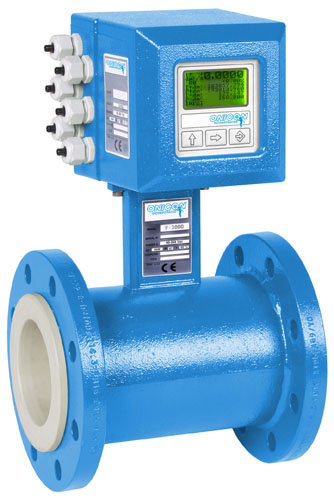
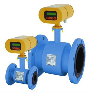
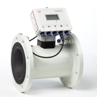
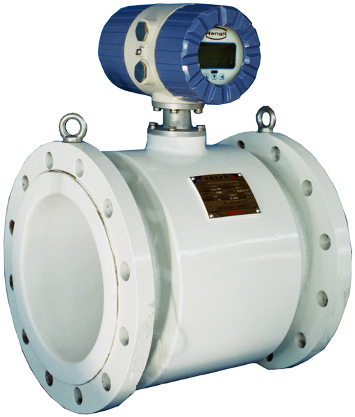
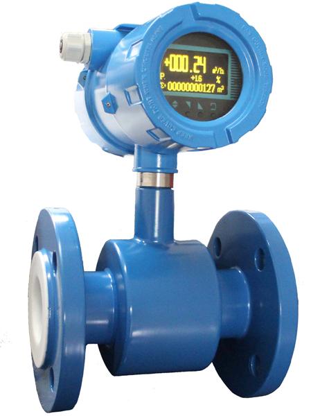
Magnetic flow meters, often called "mag meter"s or "electromag"s, use a magnetic field applied to the metering tube, which results in a potential difference proportional to the flow velocity perpendicular to the flux lines. The potential difference is sensed by electrodes aligned perpendicular to the flow and the applied magnetic field. The physical principle at work is Faraday's law of electromagnetic induction. The magnetic flow meter requires a conducting fluid and a nonconducting pipe liner. The electrodes must not corrode in contact with the process fluid; some magnetic flowmeters have auxiliary transducers installed to clean the electrodes in place. The applied magnetic field is pulsed, which allows the flowmeter to cancel out the effect of stray voltage in the piping system.
A Lorentz force velocimetry system is called Lorentz force flowmeter (LFF). A LFF measures the integrated or bulk Lorentz force resulting from the interaction between a liquid metal in motion and an applied magnetic field. In this case the characteristic length of the magnetic field is of the same order of magnitude as the dimensions of the channel. It must be addressed that in the case where localized magnetic fields are used, it is possible to perform local velocity measurements and thus the term Lorentz force velocimeter is used.
Ultrasonic Doppler flow meters measure the Doppler shift resulting from reflecting an ultrasonic beam off the particulates in flowing fluid. The frequency of the transmitted beam is affected by the movement of the particles; this frequency shift can be used to calculate the fluid velocity. For the Doppler principle to work there must be a high enough density of sonically reflective materials such as solid particles or air bubbles suspended in the fluid. This is in direct contrast to an ultrasonic transit time flow meter, where bubbles and solid particles reduce the accuracy of the measurement. Due to the dependency on these particles there are limited applications for Doppler flow meters. This technology is also known as acoustic Doppler velocimetry.
One advantage of ultrasonic flow meters is that they can effectively measure the flow rates for a wide variety of fluids, as long as the speed of sound through that fluid is known. For example, ultrasonic flow meters are used for the measurement of such diverse fluids a liquid natural gas (LNG) and blood. One can also calculate the expected speed of sound for a given fluid; this can be compared to the speed of sound empirically measured by an ultrasonic flow meter for the purposes of monitoring the quality of the flow meter's measurements. A drop in quality is an indication that the meter needs servicing.
Using the Coriolis effect that causes a laterally vibrating tube to distort, a direct measurement of mass flow can be obtained in a coriolis flow meter. Furthermore, a direct measure of the density of the fluid is obtained. Coriolis measurement can be very accurate irrespective of the type of gas or liquid that is measured; the same measurement tube can be used for hydrogen gas and bitumen without recalibration.
Coriolis flow meters can be used for the measurement of natural gas flow.
Laser Doppler flow measurement
A beam of laser light impinging on a moving particle will be partially scattered with a change in wavelength proportional to the particle's speed (the Doppler effect). A laser Doppler velocimeter (LDV), also called a laser Doppler anemometer (LDA), focuses a laser beam into a small volume in a flowing fluid containing small particles (naturally occurring or induced). The particles scatter the light with a Doppler shift. Analysis of this shifted wavelength can be used to directly, and with great precision, determine the speed of the particle and thus a close approximation of the fluid velocity.
A number of different techniques and device configurations are available for determining the Doppler shift. All use a photodetector (typically an avalanche photodiode) to convert the light into an electrical waveform for analysis. In most devices, the original laser light is divided into two beams. In one general LDV class, the two beams are made to intersect at their focal points where they interfere and generate a set of straight fringes. The sensor is then aligned to the flow such that the fringes are perpendicular to the flow direction. As particles pass through the fringes, the Doppler-shifted light is collected into the photodetector. In another general LDV class, one beam is used as a reference and the other is Doppler-scattered. Both beams are then collected onto the photodetector where optical heterodyne detection is used to extract the Doppler signal.
Even though ideally the flowmeter should be unaffected by its environment, in practice this is unlikely to be the case. Often measurement errors originate from incorrect installation or other environment dependent factors In situ methods are used when flow meter is calibrated in the correct flow conditions.
Transit time method
For pipe flows a so-called transit time method is applied where a radiotracer is injected as a pulse into the measured flow. The transit time is defined with the help of radiation detectors placed on the outside of the pipe. The volume flow is obtained by multiplying the measured average fluid flow velocity by the inner pipe cross section. This reference flow value is compared with the simultaneous flow value given by the flow measurement to be calibrated.
The procedure is standardised (ISO 2975/VII for liquids and BS 5857-2.4 for gases). The best accredited measurement uncertainty for liquids and gases is 0.5%.
Transit time animation
Tracer dilution method
The radiotracer dilution method is used to calibrate open channel flow measurements. A solution with a known tracer concentration is injected at a constant known velocity into the channel flow. Downstream where the tracer solution is thoroughly mixed over the flow cross section, a continuous sample is taken and its tracer concentration in relation to that of the injected solution is determined. The flow reference value is determined by using the tracer balance condition between the injected tracer flow and the diluting flow..
The procedure is standardised (ISO 9555-1 and ISO 9555-2 for liquid flow in open channels). The best accredited measurement uncertainty is 1%